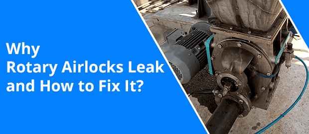
One of the most efficient machinery, the Rotary Airlock Valve (RAV) is utilised for bulk material handling as it helps maintain consistent pressure differential and controlled feeding. The valves serve as a lock that prevents air loss alongside performing vital material handling functions. They are primarily used around the airlock pneumatic conveying in high velocity, metered drop through, and feeding solutions.
Though simple, the rotary airlock valve is a significant component responsible for the efficiency of a pneumatic conveying system. In this read, we have highlighted the working of rotary airlock valves, their types, reasons for leakage in the equipment, and rotary airlock leakage solutions.
A] The Working of Rotary Airlock Valves
The working of rotary airlock valves (or rotary feeders, rotary valves) isn’t very complex.
- The product or material to be handled (conveyed) is put into the equipment first.
- The product slowly discharges into the conveying pipe at the same time the internal rotor of the valve rotates. This provides a seal between the atmospheric conditions within the bin and the pressure conveying product inside the pipe.
- This enables the materials to travel down through the valve from the inlet to the outlet port while giving an airlock effect.
- The materials move continuously through constant air pressure between these ports. This ensures that the pressure or vacuum difference is thoroughly maintained within the valve for its proper functioning.
Rotary valves are crafted in varied sizes, and the speed of rotation provides a governed material throughput. Its volumetric filling capacity ranges from 50 – 80% of the actual volume, and the maximum speed limit needs to be less than 35 rpm.
Discover the Secrets to Fixing Rotary Airlock Leaks
B] Types of Rotary Airlock Valves
- Drop-Through Valve: The Drop-Through Valve is often used to meter material from bins and hoppers. The material fed in it is dropped through the inlet, while the rotating vanes move the material down, dropping it out of the outlet at the bottom via gravity. This type of rotary airlock valve is commonly used in systems with dust collector and hopper discharges that require a seal between the atmosphere and the vacuum.
- Blow -Through Valve: In the Blow-Through Valve configuration, the conveying pipes are connected to & from the endplate. The way the material is put into the inlet is similar to drop-through. But, as the material passes through the valve’s underside, it is blown out directly of the rotor pockets into the conveying line downstream. The blow-through valve is the best choice for conveying non-abrasive powders such as flour.
C] Why Do Rotary Airlocks Leak: Rotary Airlock Leakage Problems
Generally, there are two types of rotary airlock leakage problems: Clearance leakage and Displacement leakage. Worn-out shafts (though unrelated) can also lead to leakages.
1. Clearance Leakage
Clearance leakage occurs through the blade-to-housing and blade-to-headplate clearances after material enters the valve.
Rotary airlock valves do not come with a 100 % seal as it is required to have a small clearance between the housing and rotor blades for seamless rotation & operation. However, if the clearance between the rotor and housing rises above the set index, it can become an issue.
Any gap bigger than required will compromise the ability of the valve to act as an airlock and increase the chances of creating a combustible dust hazard. Thus, the clearances need to stay below the recommended size to get the best output in each rotor pocket, thereby reducing waste and preventing hazards.
The exact clearance is determined by various factors such as speed, temperature & thermal expansion, displacement of the housing under the material load, and rotor run-out.
2. Displacement Leakage
While some amount of air leaks out of the small clearance when the material enters the valve, some of it stays inside the rotor as it meets pressure at the outlet. When the trapped air comes around to the inlet, it releases into the feed hopper, which hampers the material flow.
Displacement leakage can be defined as the amount of air that enters each rotor pocket as the pocket passes the material outlet. The leakage only increases with the valve’s running speed and actual displacement.
Various factors like pressure differential across the valve, rotor pocket volume, product feed rate, and valve shaft speed determines the amount of rotor displacement leakage.
3. Worn-out Shaft Seals
Worn-out shaft seals can also be a cause of leakage. When the shaft seal is worn heavily, the material will contaminate the bearing, eventually causing the bearing to fail. This ultimately means more material leakage leading to expensive repairs.
The expected total air leakage through the valve is calculated by summing the clearance leakage and displacement leakage estimated by the valve manufacturer. Operators may notice an increase in the conveying system’s air requirement or drop-in material throughput if the valve’s air leakage is excessive.
Discover the Secrets to Fixing Rotary Airlock Leaks
D] Rotary Airlock Leakage Solutions
1. Regular Maintenance
The waste material from the leakage can cause downtime and wear down other valve parts. Therefore, it is essential to use the right maintenance methods to diagnose, prevent or repair these leakages.
- Ensure to regularly check the rotor-to-housing tolerances and replace the rotor in case the blades have worn down.
- Make sure to use precise measurements for replacements to avoid misfits.
- In cases where replacement doesn’t seem necessary, a rotary airlock repair will be sufficient. Just keep spare shaft seals and packing handy.
2. Install Flexible Strips
This is another effective rotary airlock leakage solution. To minimise Clearance leakage, you can:
- Install flexible seal strips
- Or select a valve with a higher number of rotor blades
Out of the two, installation of flexible seal strips is an easy and effective solution.
3. Attach the Valve Directly to the Storage Vessel
You can directly attach the rotary airlock valve to the vessel that stores the material being moved to the conveyor system. It allows the valve to serve as an airlock as well as a metering design for the conveying line.
Here, the air produced from the rotary airlock leakage will go straight into the storage vessel, moving through the material in the storage and finally, venting from the top of the vessel.
The vessel often contains a bin vent filter capable of exhausting the leaked air. Also, ensure that the rotary airlock valve pocket vent is connected to the hopper for efficient venting.
4. Equip the Valve with a Surge Hopper
Another solution is to equip the valve with a surge hopper that comprises a dedicated vent filter. The vented surge hopper can be fed in three different methods when sized proportionally to the airlock. These includes:
- Feeding by another rotary airlock valve located below a storage vessel
- Acting as a transition to a metered feed point
- Being flood-fed from a storage vessel
5. Collect the Leaked Air in a Central Dust Collection System
The leaked air can also be contained in the plant’s central dust collection system. Here, the dust collection fan provides a negative draft to ensure that the leaked air follows a trail through the surge hopper & its vent until it reaches the dust collection system.
Discover the Secrets to Fixing Rotary Airlock Leaks
Conclusion
Leakages may occur frequently in rotary airlock valves, more often depending upon the quality and durability of the valve and its maintenance. Before you attempt to fix these leakage problems, you may want to consult with an experienced professional. They can provide the right rotary airlock leakage solutions according to the type of equipment you are using.
For more queries, get in touch with us.

Kedar Kamath
Kedar Kamath is a highly accomplished bulk material handling professional with 14+ years of experience at Macawber Engineering Systems India Pvt Ltd. Starting as a junior sales engineer, he progressed to his current role heading Business Development and Sales. His expertise encompasses proposals, estimations, sales, marketing, design engineering, project execution, and factory operations. Mentored by industry leaders, Kedar's technical acumen (B.Tech in Electrical Engineering, VJTI, Mumbai) and innovative approach deliver tailored solutions. He's passionate about sustainable practices and driving excellence within the industry.


